The electromechanical timer of my washing machine died. It couldn't be repaired and had to be replaced.
What to do?
- Be boring, go to the store, buy a new one, replace it
- Build your own, even if you have no idea how
If you think the second option is the right one keep reading...
Background
It's 2007. My great old washing machine (an Aurora T-5502) got stuck while in the spin cycle and spun for hours. When I found out it was too late and there was already some damage in the machine.
Cause? The electromechanical timer. It was worn-out and the contacts couldn't rotate as originally designed. The old timer couldn't be repaired and has to be replaced.
The timer was like an old fashioned clock, where the hand touches different contacts along the way, activating different functions.
That's grandpa tech. I needed something better.
No long ago I had read about microcontrollers and got fascinated about the topic. So I decided to make my own electronic timer, which should be cooler.
DISCLAIMER: As I said, I had almost no idea of electronics when I started the project, so don't kill me for all the wrong choices.
The finished project
Don't want to bore you with details, so let me show you how it went and leave the rest for the end in case you still interested.
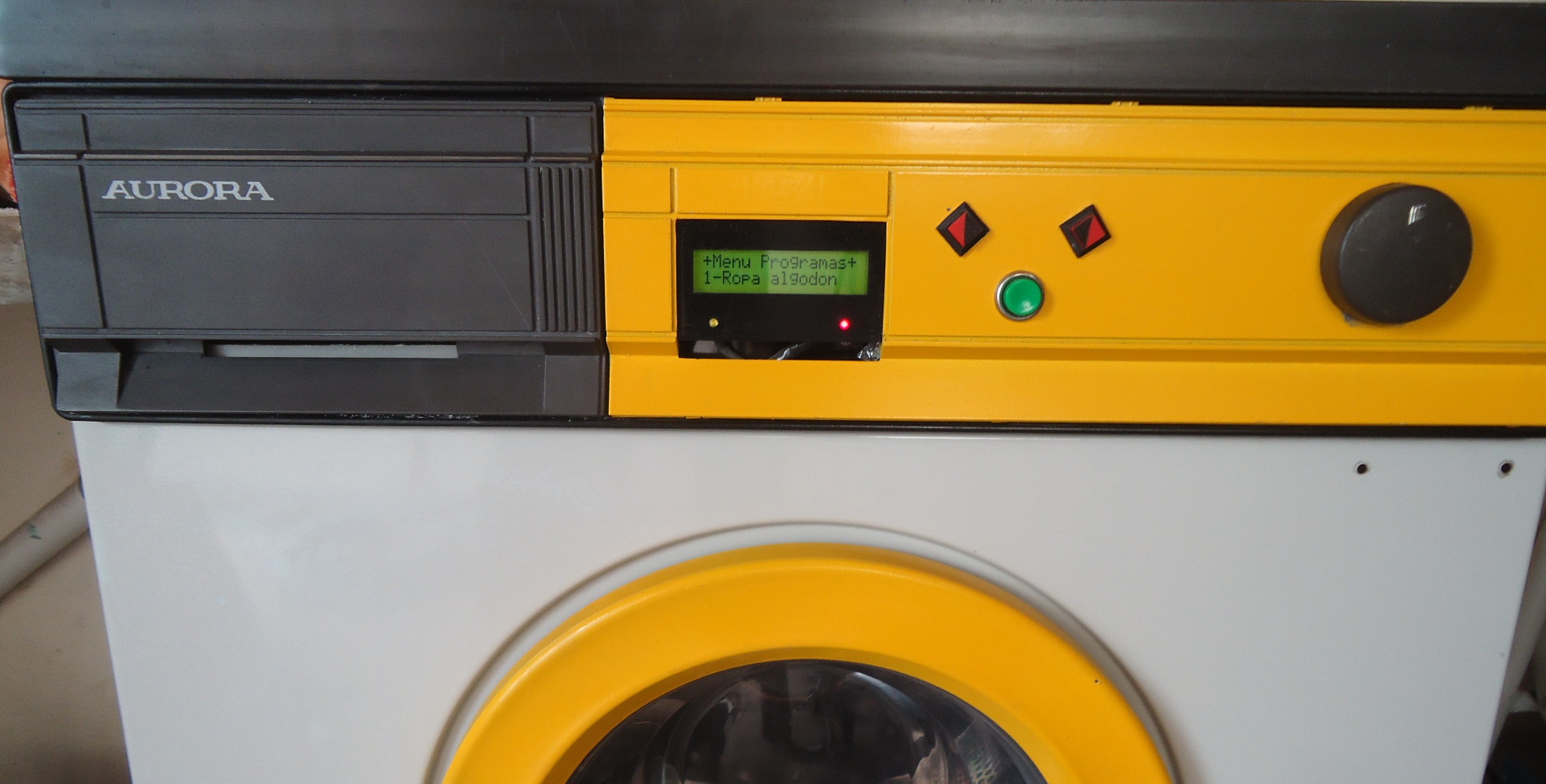
The machine provides 4 different full programs, 2 short ones, and configuration:
- Ropa de algodón (cotton)
- Ropa delicada (delicate)
- Ropa muy sucia (very dirty)
- Modo agresivo (aggressive mode)
- Drain
- Spin only
- Configuration
For each program following parameters can also be selected:
- Prewash
- Temperature
- Disable spin cycle
- Initial delay
UPDATE 2014: I added uploaded some videos to youtube.
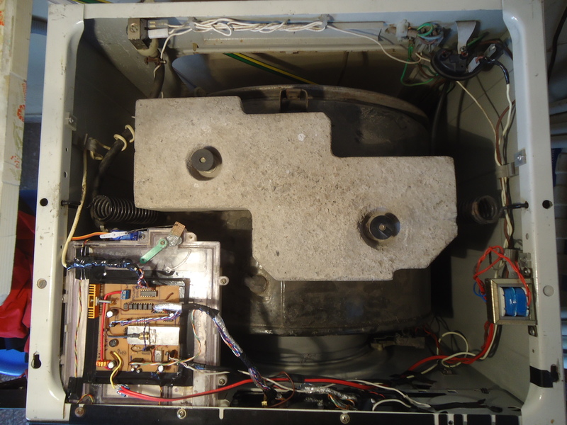
Washing machine internals
The system is divided in three parts:
- The control panel
- The motherboard
- The interface with the washing machine
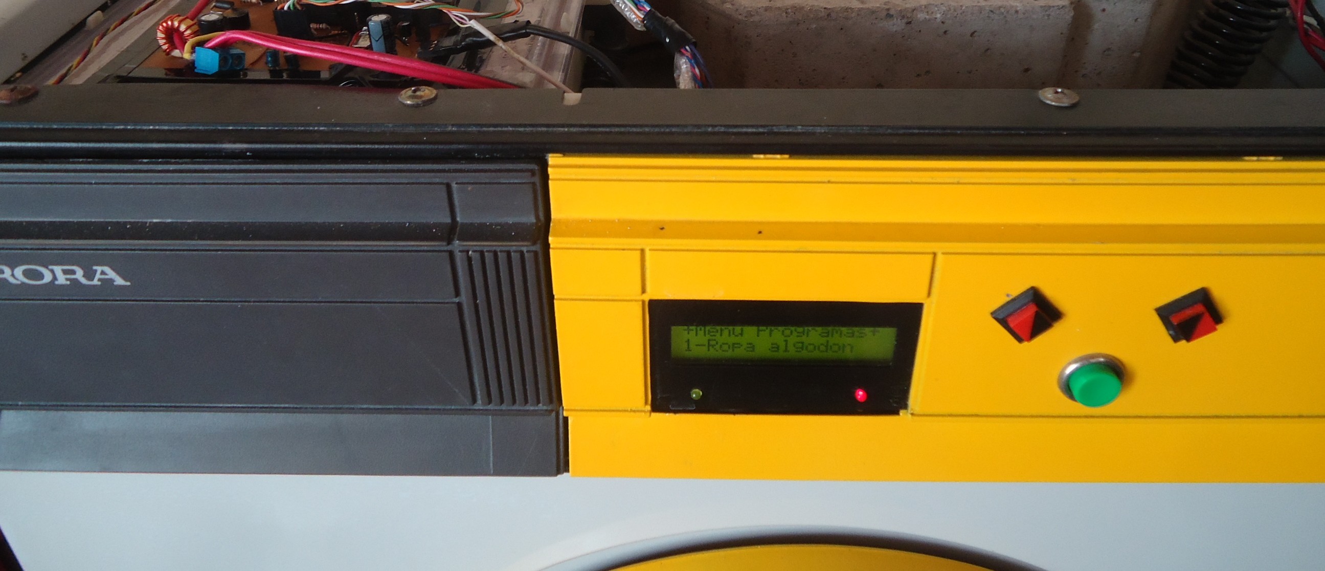
The control panel
It's the interface with the user. Contains:
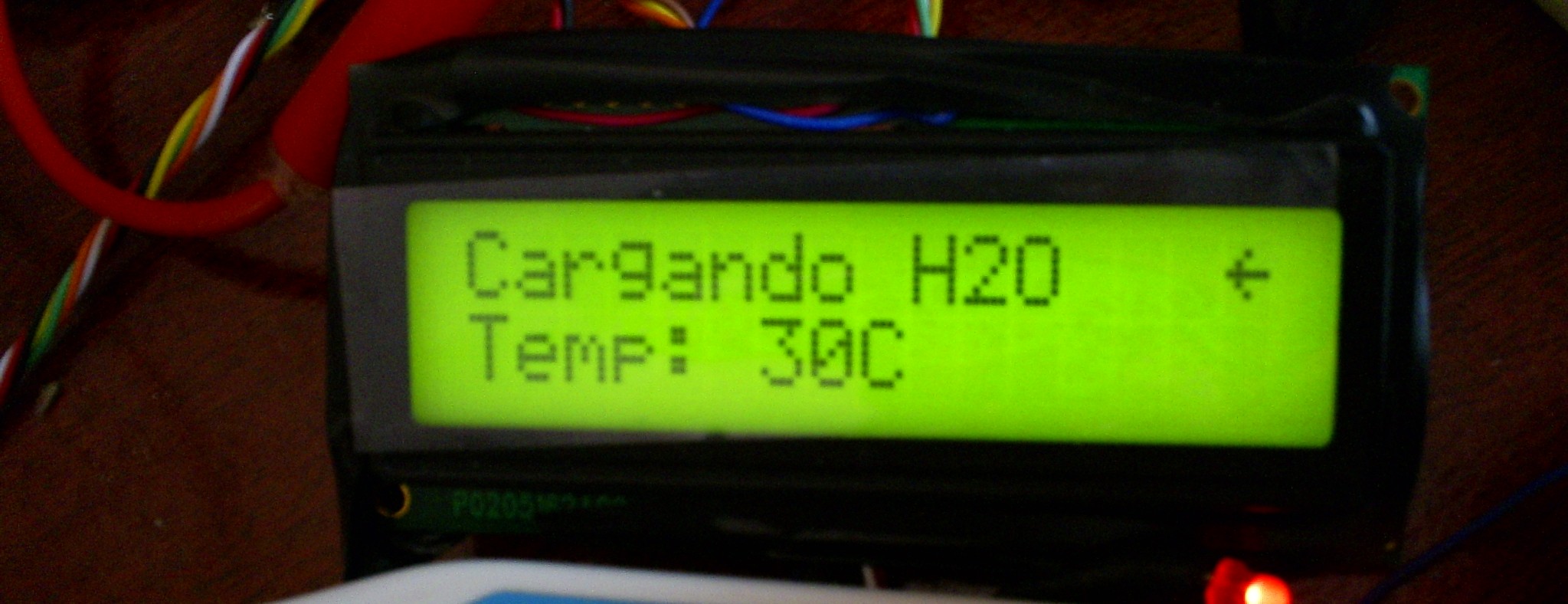
- LCD screen (16x2)
- 3 buttons (Left, Right, Enter)
- Red power led (to show the power stage is working)
- Yellow led (show established link to pc, if connected)
- Piezoelectric sounder (to generate tones)
The LCD has his own driver (microcontroller). Mine was the HD44780, and the protocol can be found on the datasheet. I used a library which spared me the headache. Sadly the driver is very sensitive to EMI, which caused a LOT of trouble.
A special consideration is required with the buttons, specially if you buy cheap ones: when you press the button the metallic pieces bounce at an almost microscopic level. In many cases the bounce interrupts the electric flow up to many times for some microseconds before completely close the circuit as expected to. As the microcontroller is fast enough it could wrongly sense many presses of the button even if you only pressed it once.
There is two solutions:
- Hardware filters (low pass)
- Filter it by software
The sounder is connected directly to the microcontroller, being able to generate a wide range of tones.
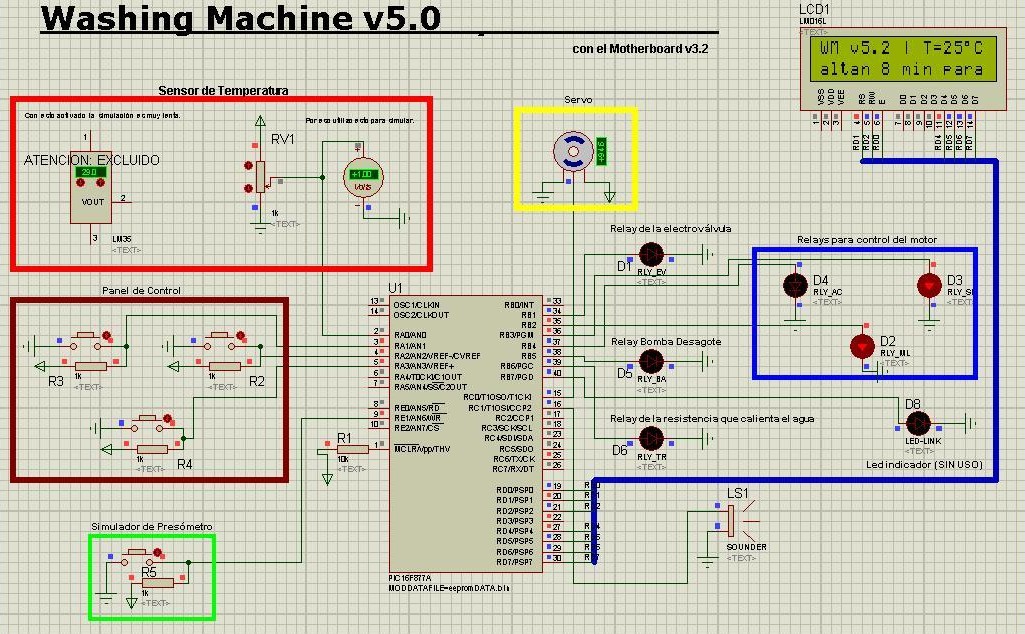
The motherboard
It's the central part of the design. It hosts the microcontroller and connects it with the peripherals.
The design was made with Eagle CAD. You can find it on Github.
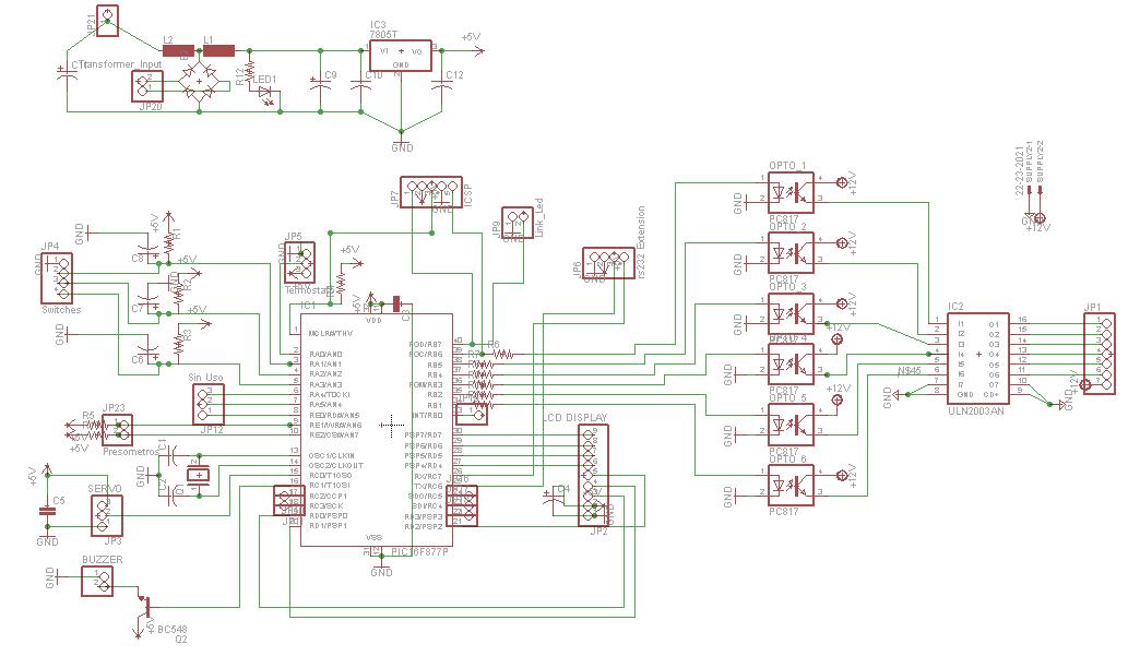
The PCB it's made of cheap Pertinax (FR-2) to save some money. No high frequencies to justify a higher quality.
The first thing is the power source. The input voltage is 9VAC 1A (a 220v/9v transformer with fuse). The motherboard contains a diode bridge to obtain 12VDC for the relays and the servo and voltage regulator (LM7805) to power the LCD and the micro at 5VDC.
Peripherals are connected to the mainboard trough housing connectors, making removal of the motherboard very easy.
The microcontroller used is the PIC 16F877PI with at 4Mhz. There was no need to run at a higher frequency. It also worked better at this frequency with the tone generator library for the piezo sounder.
To program it there is a ICSP socket, to allow direct firmware updates without having to extract the micro.
There is optical isolation with the power stage using optocouplers (HPCL-817).
The firmware is C code compiled with the PCM compiler from CCS, a very good PIC compilers of that time. The firmware uses about 85% of the ROM and required some nasty tricks to fit them in.
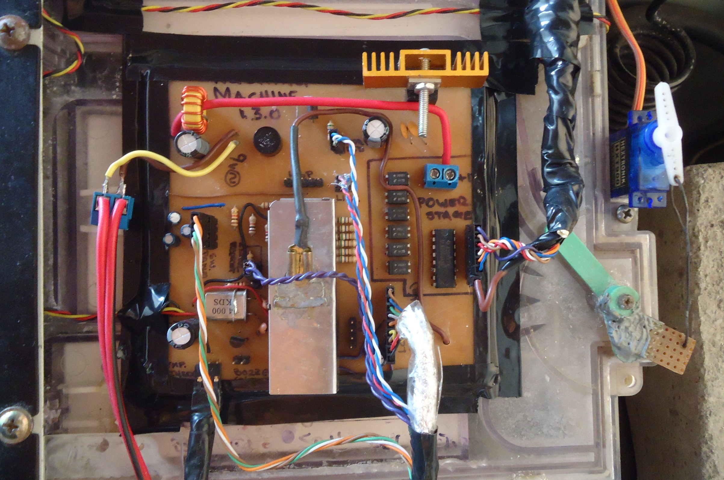
Interface with the washing machine
Power stage
It consists in a 'panel' of relays, acting as switches to control the electric flow to the different components of the machine:
The panel diagram:
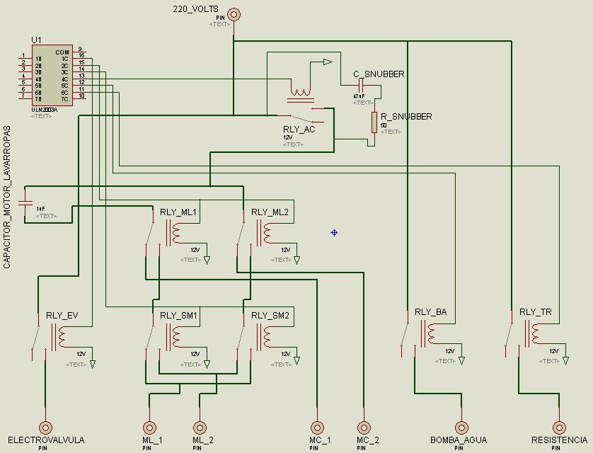
The actual panel:
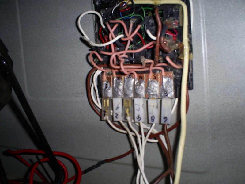
- Electrovalve(RLY_EV): an electrically controlled water inlet. It let water flow when an electrical current is applied. The water goes directly to the dispenser system
- The heater(RLY_TR): a resistance to heat the water
- Drain pump(RLY_BA): to extract the water from the wash drum
- The motor(RLY_AC, RLY_ML1, RLY_ML2, RLY_SM1, RLY_SM2): provides the rotation of the drum. My machine has one motor with 2 different coils. One for slow speed and one for the spin cycle.
The connections to Electrovalve, Heater and Pump were relatively straightforward. So I will omit the explanation.
To interface the motor I had to do some experimentation to find out how to make it work. These are the results:
Lets assign numbers to the connector pins (from left to right). The upper row 1, 2, 3 and 4, 5, 6 to the bottom row.
| Pin number | |
|---|---|
| 1 | GND |
| 2 | High Speed Coil (MC_1) |
| 3 | Low Speed Coil (ML_1) |
| 4 | GND |
| 5 | High Speed Coil (MC_2) |
| 6 | Low Speed Coil (ML_2) |
NOTE: The electrolytic condenser (CAPACITOR_MOTOR_LAVARROPAS) is shared within the two coils.
The relays RLY_MLx makes the commutation between low speed coil (for normal washing) ML_x and high speed one (for spinning) MC_x.
When the low speed coil is active, the relays RLY_SM control the direction of rotation (see panel diagram). When the high speed coil is active they have no effect.
The relay RLY_AC switch the motor on and off. The snubber reduces the EMI of the commutation, which is horrible for big inductive loads like the motor.
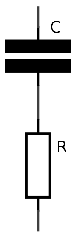
The snubber configuration used (ignore the values of the diagram):
- R=100Ohm/1Watt
- C=100nF/250V
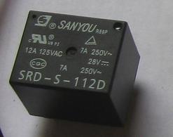
The relays I used are SANYOU SRD-S-112D, the are very cheap. I end up using it in pairs instead of buyin double pole ones.
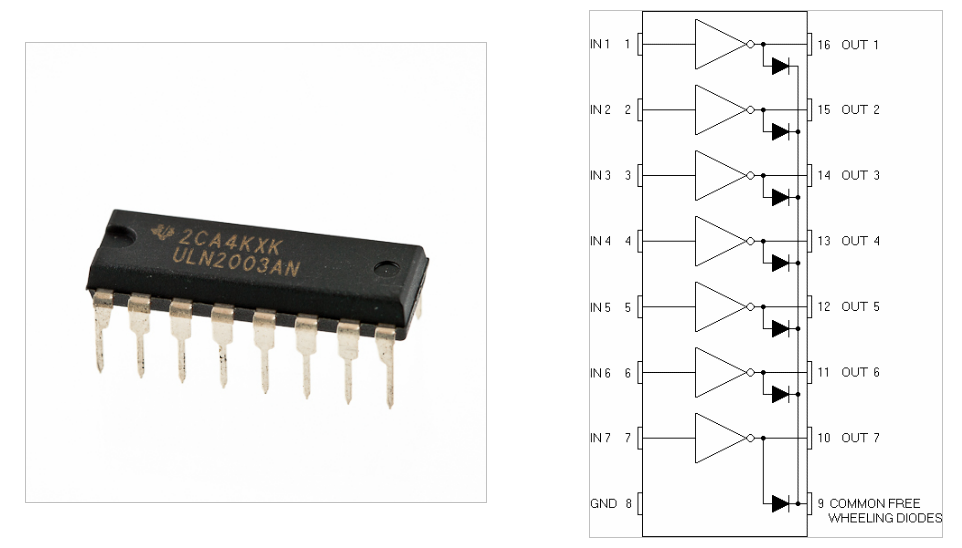
To control the relays I used an array of Darlington transistors (ULN2003AN). Each Darlington comes with a freewheeling diode, to protect the transistors from coil auto induction, when driving inductive loads.
Sensors
Pressure switch: allows to know when the water reached
a predefined level by measuring the air pressure exert by the water
in a special air chamber. It's used as a normal switch.
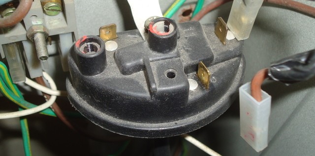
Door switch: actually a main switch, which is closed only by the door. When the door closes the machine is turned on. I keep using it as originally designed. The door switch doesn't contains any lock mechanism.
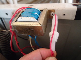
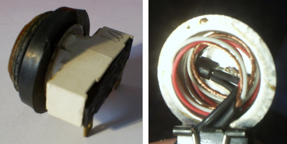
Temperature sensor: originally was a bimetalic thermostat to measure water temperature and control the heater. I completely replaced it with a LM35 temperature sensor reusing the original metallic housing of the thermostat. The LM35 was attached to the housing using super glue.
Dispenser system
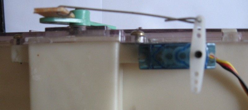
This machine has only one water inlet and a rotatory arm to divert the water flow into the different compartments. The arm was originally controlled by the electromechanical timer. To achieve the same function I used a low cost servo for model airplanes (I took the idea from Pablo Canello)
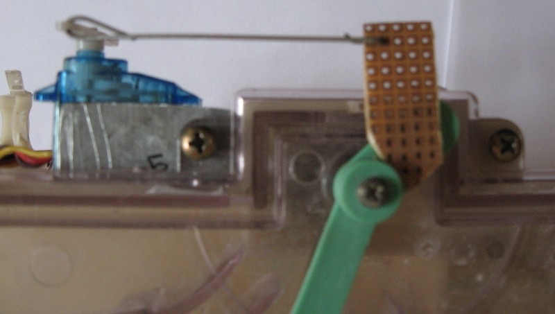
The servo was attached to the rotatory arm (green) using a little bit of bricolage ingenuity.
Check this video to see exactly how it works.
The servo has 3 lines, VCC, GND and signal. To control the servo position the PIC will generate a PWM signal at 50Hz. Varying the pulse within 1ms to aprox 2.5ms will be linearly translated to 0 degrees and 180 degrees respectively.
As long the PWM signal is present, the servo will do all it can to get to the desired position. If the signal is interrupted the servo remains in its last position and will not try to correct externally applied forces
Every time before loading water, the servo will be positioned in the corresponding compartment.
To correctly move the rotatory arm, the servo position corresponding to each compartment of the dispenser will be recorded with help of a calibration routine (a once time operation). Each position is a value between 0 and 255 (one byte) and will be stored in the PIC EEPROM.
Operation
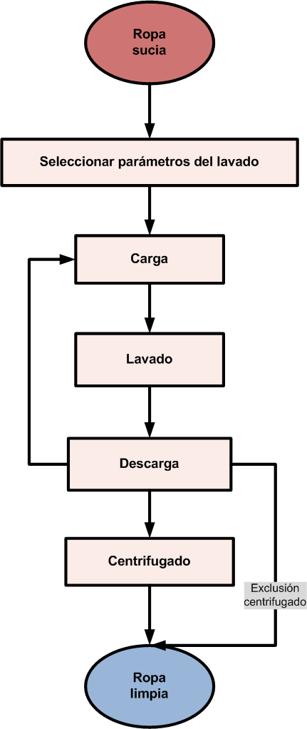
Simplifying a little, the operation starts by selecting the washing parameters.
It's followed by many cycles of the following tasks:
- Select the desired compartiment on the dispenser system
- Load water until pressure switch closes
- Wash alternating directions
- Pump water out
The operation finishes with the spinning cycle (if the spin option wasn't excluded when selecting the parameters).
Each task has its own parameters which varies between all the washing programs. Please refer to the code to see the differences.
Hardware versions
The motherboard went through 3 different iterations:
Version 1
The proof of concept. It was a RS232 interface between the washing machine and the PC. The power stage and the sensors where connected to a PIC 16F84A.
The user interface was a computer program which sent orders to the PIC UART through a serial interface.
Version 2
I grew up my skills on microcontrollers so I went for an autonomous solution. A new set of features were added:
- LCD screen with HD44780 microcontroller
- Buttons
- Piezoelectric sounder
Therefore a more powerful microcontroller came into play. The amazing PIC 16F877PI.
The biggest problem with this version was random freezes on the PIC. It was very hard to get the program to finished after installing it on the machine. Outside all tests and simulation worked perfectly. I almost went crazy with this problem.
Version 3
After realizing that the freezing problem was electromagnetic noise (EMI), I put all my effort (really felt clueless most of the time) to eradicate it:
- Filters on the power supply
- Galvanic isolation from the power stage (with optocouplers)
- Decoupling capacitors (between VCC and GND)
- A Faraday cage (sort of) for the PIC connected to GND
- Better PCB design
It improved the stability of the system a lot, but still had some sporadic problems. After some more debugging I discovered that the LCD display was also being affected by EMI and as result it was blocking the execution of the program.
I applied 2 extra measures:
- Snubbers on the relays to reduce EMI emission (they make a hell of a mess when commuting, especially the motor)
- Faraday cage to the LCD circuit (as much as possible)
Firmware history
Version 1
The interface between the PIC 16F84A and the PC. A bidirectional communication implemented with a software based UART.
The PC was responsible to send the desired output and servo position, and it received the state of the sensors.
Version 2
Designed to match the new ambitious plans, and the power of the 2nd hardware generation.
I tried to leverage the power of a real time operating system. Therefore I used CCS-RTOS, programming every process as a different task:
- LCD update
- Temperature regulation
- Servo position update
- etc.
without having to worry about the coordination between them.
It was a failure because of the stack overflows. They were a lot of tasks, and the PIC has only a 8 bytes stack.
Version 3
A minimalistic sequential version. No RTOS.
There was only one washing program. The LCD display isn't updated while washing.
Version 4
I borrowed a lot of the nice ideas of using a RTOS and introduced it in the sequential version to obtain a similar behaviour.
Different washing programs were added, and the EEPROM is used to resume after a power failure.
The display is updated while the washing task are running. Now we are talking!
Version 5
Basically a lot of small improvements:
- New menu to:
- Select washing temperature
- Prewash
- Exclude spinning
- Initial delay
- Better temperature sensing algorithm
- Improved relay switching to reduce wear out
Sources
Update 2014: You can find the sources and designs in Github.
If something wrong or missing just drop me a line.
Acknowledgements
I got a lot of inspiration and ideas from Pablo Canelo and his washing machine.